Friday, September 7, 2018

Water Pump Control With Tank Level

Water Pump Control With Tank Level

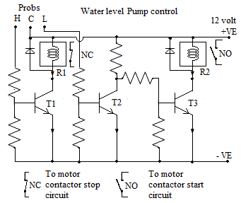
Introduction:- This circuit is designed to switch off water pump when water level is high in tank. When the water level in tank is below a set level it will start pump automatically.
This circuit consist of three transistors and two relays with some Resistace etc it work on 12 volt supply. First relay R1 serves  as stopping relay and ssecond relay R2 serves as starting relay. When water level goes below set level say 20 % of full tank start relay will pick up. With NO contact of R2 relay pump motor contactor will picks up and motor switch on. When tank will fill up completely first relay R1  will pick up with NC contact of first relay R1 pump motor contactor will switch off.

Senser:- There are three senser prob of conductive material is used. First one is common , second one is for high level and third one is for low level.


Circuit :- 12 volt supply is given to common prob. high level prob tip is set at a hight where pump is to be stop. When pump is running water level goes on increasing in tank. When water surface touches the high lebel prob the 12 volt of common prob will reach to high level prob. This high level prob is connected to base of transistor T1. With this transistor T1 will conduct and relay R1 will pick up. So the NC contact of relay R1 will open and pump contactor dropped out hence motor get stopped. With the use of water, tank water level goes on decreasing .When the water level decreases to a point where low level prob tip is placed the contact of water surface to prob will brake. As this prob is connected to base of transistor T2, the base volage of transistor T2 become zero hence transistor T2 will cut off.  So collector voltage of transistor T2 become 5 volt so it will give base biasing to transistor T3. with the base biasing transistor T3 will conduct and relay R2 will picks up. With the NO contact of relay R2 motor contactor will picks up and hold on. After slightly fill up, the water level touch the low level prob so relay R2 drops down but pump will still runs continue because of motor contactor hold on. Again at high level pump will stop with relay R1.


https://vijayelectronicsforu.blogspot.com/2018/08/star-delta-starter-principle-circuit.html

https://vijayelectronicsforu.blogspot.com/2018/07/dc-motor-direction-control-by-two-relay.html


Wednesday, September 5, 2018

Classification of Three Phase Motors

Classification of Three Phase Motors

Three Phase induction motors are classified on the basis of working voltage and there construction.
Classification on the basis of operating voltage:- 

1. HT motors:- These motors works on high voltage 11 kv, 6.6 kv etc. normally motors above 500 kw is comes with high voltage winding. H T motors are used in very big industries for heavy loads like Exhaustors fans, Induced draft fans, very big compressors etc. These motor are  of two types first one is synchronous motor. Synchronous motor stator consist of three phase high voltage winding. Rotor is generally sailient pole type with 4 pole ( same as stator winding ) dc winding normally 24 to 50 volt dc with 200 to 300 ampere ( 1MW motor). In addition to this dc winding rotor has also a damper winding made of solid copper conductor on the rotor pole face. This damper winding provide the starting torque to rotor whi!e starting and reduce huntung of motor during running. The power factor of synchronous motor can be adjusted with rotor current ( excitation current) so these motors are also used for power factor correction purpose. The second is simple induction motor.


2. LV motors:- these motors are working at 415 vac.

Classification on the basis of rotor winding:-

1. Squirrel cage induction motor:- These motors are having 3 phase winding in stator and a squirrel cage winding in rotor. The squirrel cage winding consist of  solid conductors of copper or alluminium in rotor slots with short circuiting end ring on both sides. These  motors are used with direct on line starter or star delta starter. The starting torque of motor is 350 percent of full load torque. These motors are used in floor mills, belt conveyors, ventilation  fans, compressors  in industry. These motors runs at approximatly constant speed near synchronous speed. Some double speed motors are also comes. The speed control of squirrel cage induction motor is done with the help variable voltage variable frequency drives.        2. Slip ring motor or wound rotor motor:- In this type of motor stator has 3 phase winding. Rotor has also three phase winding connected in star connection. Three leads of rotor winding is connected to slipring mounted on shaft. External connection to slipring is given with  help of  carbon brushes. In slipring motor 3 phase supply is given to stator and a three phase star connected external resistance is inserted in rotor circuit. At starting full resistance is kept in rotor circuit as speed increses gradually all resistance is cutoff that is external resistance is short circuited. The benifit of slipring motor is that  its maximum torque can be obtain from initial speed to full load speed. Slipring motors are used in electrcal overhead cranes where high starting  torque is required. 

Tuesday, September 4, 2018

मल्टी मीटर का उपयोग करना

मल्टी मीटर का उपयोग करना

भूमिका:- इलेक्ट्रॉनिक रिपेरिंग में मल्टी मीटर का बहुत ज़्यादा उपयोग होता है। मल्टी मीटर के द्वारा वोल्टेज करेन्ट रेजिस्टेंस आदि आसानी से नापे जा सकते हैँ।
सानवा p3 मल्टी मीटर में निम्नलिखित रेँज होती हैं।                     
रेजिस्टेंस
कॉन्टीन्यूटी के लिये दो रेंज होती हें पहली 10 k, इसमें 0 से 10 किलो ओम तक का रेजिस्टेंस नाप सकते हैं।
दूसरी रेंज 1 मेगा ओम की होती है जिसमे 0 ओम से 1 मेगा ओम तक रेजिस्टेंस नाप सकते हें तथा कॉन्टिन्यूटी चेक कर सकते हें।                                                             
डी सी मिली एम्पीयर के लिए तीन रेँज होती हैं  पहली 0.25 ma इसमें 0 से 0.25 ma तक करेन्ट नाप सकते हैं। दूसरी रेंज 10 ma की होती हे जिसमे 0 से 10 ma तक नाप सकते हैं। तीसरी रेंज 250 ma की होती हे जिसमें 0 से 250 ma तक करेंट नाप सकते हैं।                                                                                                            डी सी वोल्टेज के लिये चार रेंज होती हैं पहली 10 volt की जिसमे 0 से 10 वोल्ट तक नाप सकते हैं दूसरी 50 volt की होती हे जिसमे 0 से 50 वोल्ट तक नाप सकते हैं।

तीसरी 250 वोल्ट डी सी की रेंज होती हे जिसमे 0 से 250 वोल्ट डी सी वोल्टेज नाप सकते हैं। चोथी 1000 वोल्ट डी सी की होती हे जिसमें 0 से 1000 वोल्टेज तक नाप सकते हैं। इसी प्रकार ए सी वोल्टेज नापने के लिये 5 रेंज होती हैं। जो की 10 वोल्ट, 50 वोल्ट, 250 वोल्ट, 500 वोल्ट और 1000 वोल्ट ए सी नापने के काम आती हैं । रेजिस्टेंस नापने के लिये ब्लैक प्रोब को कॉमन में तथा रेड प्रोब को 10 K या 1M के पॉइंट में लगाते हैं। वोल्टेज व कर्रेंट नापने के लिये ब्लैक को कॉमन में तथा रेड प्रोब को जितना वोल्टेज नापना है उसी पॉइंट में लगाते हैं ।सावधानी:- वोल्टेज नापते समय प्रोब का मेटल हाथ से टच नहीं होना चाहिए। सही रेंज का सिलेक्शन करना चाहिये । कुछ मल्टी मीटर में रेंज सिलेक्शन के लिए रोटरी स्विच होता हे जिसे घुमा कर रेंज सेट करते हैं । आजकल डिजिटल मल्टी मीटर गये हे इनमे रीडिंग डिजिटल डिसप्ले पर दिखाई जाती हे। कुछ मल्टी मीटर में 10 एम्पियर नापने की रेंज भी होती हे । रेजिस्टेंस नापते समय सर्किट में सप्लाई नहीं होना चाहिए । आशा करता हूँ यह पोस्ट आपको पसंद आएगी ।

Saturday, September 1, 2018

Speaker construction and working

Speaker construction and working

Introduction:- Speaker work on the principle of electomagnetism. A current carring conductor in a magnetic field experience a mechanical force.The direction of force is given by flaming's left hand rule. The force is proportional to the magnetic field and strengh  of current. The direction of force reverse with reversing the direction of current.
Construction:- It consist of a permanent magnet with magnetic field arrengement. A moving coil made of approximately 40 to 60 turns of very thin insulated copper wire. A spider made of hard cloth type material and a paper cone. A conical structure made of metalic sheet. All items are fixed with each other as shown in diagram.


Working:- When amplified audio signal is applied to the coil of speaker coil starts vibrating according to the signal voltage. The spider and paper cone also starts vibrating. Due to the vibration of paper cone sound generete form speaker. This sound is same which is given to the input of amplifier.

Speaker are varies in size, shape, wattage, and ohms. Speaker comes in round shape, oval shape slim shape. They are comes in 5, 10, 20, 40 watts etc, ohms rating are 4 ohm 8 ohm 16 ohm 32 ohm etc.

Checking:- With multimeter we can check speaker, It will show continuty and resistance value of speaker. Also if we touch 1.5 volt supply to the speaker points it gives some sound which indicates speaker is ok. please comment for any further improvement. Thanks


http://vijayelectronicsforu.blogspot.com/2018/08/blog-post.html