Friday, September 7, 2018

Water Pump Control With Tank Level

Water Pump Control With Tank Level

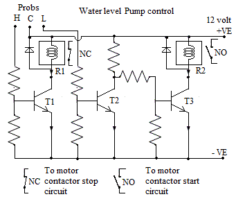
Introduction:- This circuit is designed to switch off water pump when water level is high in tank. When the water level in tank is below a set level it will start pump automatically.
This circuit consist of three transistors and two relays with some Resistace etc it work on 12 volt supply. First relay R1 serves  as stopping relay and ssecond relay R2 serves as starting relay. When water level goes below set level say 20 % of full tank start relay will pick up. With NO contact of R2 relay pump motor contactor will picks up and motor switch on. When tank will fill up completely first relay R1  will pick up with NC contact of first relay R1 pump motor contactor will switch off.

Senser:- There are three senser prob of conductive material is used. First one is common , second one is for high level and third one is for low level.


Circuit :- 12 volt supply is given to common prob. high level prob tip is set at a hight where pump is to be stop. When pump is running water level goes on increasing in tank. When water surface touches the high lebel prob the 12 volt of common prob will reach to high level prob. This high level prob is connected to base of transistor T1. With this transistor T1 will conduct and relay R1 will pick up. So the NC contact of relay R1 will open and pump contactor dropped out hence motor get stopped. With the use of water, tank water level goes on decreasing .When the water level decreases to a point where low level prob tip is placed the contact of water surface to prob will brake. As this prob is connected to base of transistor T2, the base volage of transistor T2 become zero hence transistor T2 will cut off.  So collector voltage of transistor T2 become 5 volt so it will give base biasing to transistor T3. with the base biasing transistor T3 will conduct and relay R2 will picks up. With the NO contact of relay R2 motor contactor will picks up and hold on. After slightly fill up, the water level touch the low level prob so relay R2 drops down but pump will still runs continue because of motor contactor hold on. Again at high level pump will stop with relay R1.


https://vijayelectronicsforu.blogspot.com/2018/08/star-delta-starter-principle-circuit.html

https://vijayelectronicsforu.blogspot.com/2018/07/dc-motor-direction-control-by-two-relay.html


Wednesday, September 5, 2018

Classification of Three Phase Motors

Classification of Three Phase Motors

Three Phase induction motors are classified on the basis of working voltage and there construction.
Classification on the basis of operating voltage:- 

1. HT motors:- These motors works on high voltage 11 kv, 6.6 kv etc. normally motors above 500 kw is comes with high voltage winding. H T motors are used in very big industries for heavy loads like Exhaustors fans, Induced draft fans, very big compressors etc. These motor are  of two types first one is synchronous motor. Synchronous motor stator consist of three phase high voltage winding. Rotor is generally sailient pole type with 4 pole ( same as stator winding ) dc winding normally 24 to 50 volt dc with 200 to 300 ampere ( 1MW motor). In addition to this dc winding rotor has also a damper winding made of solid copper conductor on the rotor pole face. This damper winding provide the starting torque to rotor whi!e starting and reduce huntung of motor during running. The power factor of synchronous motor can be adjusted with rotor current ( excitation current) so these motors are also used for power factor correction purpose. The second is simple induction motor.


2. LV motors:- these motors are working at 415 vac.

Classification on the basis of rotor winding:-

1. Squirrel cage induction motor:- These motors are having 3 phase winding in stator and a squirrel cage winding in rotor. The squirrel cage winding consist of  solid conductors of copper or alluminium in rotor slots with short circuiting end ring on both sides. These  motors are used with direct on line starter or star delta starter. The starting torque of motor is 350 percent of full load torque. These motors are used in floor mills, belt conveyors, ventilation  fans, compressors  in industry. These motors runs at approximatly constant speed near synchronous speed. Some double speed motors are also comes. The speed control of squirrel cage induction motor is done with the help variable voltage variable frequency drives.        2. Slip ring motor or wound rotor motor:- In this type of motor stator has 3 phase winding. Rotor has also three phase winding connected in star connection. Three leads of rotor winding is connected to slipring mounted on shaft. External connection to slipring is given with  help of  carbon brushes. In slipring motor 3 phase supply is given to stator and a three phase star connected external resistance is inserted in rotor circuit. At starting full resistance is kept in rotor circuit as speed increses gradually all resistance is cutoff that is external resistance is short circuited. The benifit of slipring motor is that  its maximum torque can be obtain from initial speed to full load speed. Slipring motors are used in electrcal overhead cranes where high starting  torque is required. 

Tuesday, September 4, 2018

मल्टी मीटर का उपयोग करना

मल्टी मीटर का उपयोग करना

भूमिका:- इलेक्ट्रॉनिक रिपेरिंग में मल्टी मीटर का बहुत ज़्यादा उपयोग होता है। मल्टी मीटर के द्वारा वोल्टेज करेन्ट रेजिस्टेंस आदि आसानी से नापे जा सकते हैँ।
सानवा p3 मल्टी मीटर में निम्नलिखित रेँज होती हैं।                     
रेजिस्टेंस
कॉन्टीन्यूटी के लिये दो रेंज होती हें पहली 10 k, इसमें 0 से 10 किलो ओम तक का रेजिस्टेंस नाप सकते हैं।
दूसरी रेंज 1 मेगा ओम की होती है जिसमे 0 ओम से 1 मेगा ओम तक रेजिस्टेंस नाप सकते हें तथा कॉन्टिन्यूटी चेक कर सकते हें।                                                             
डी सी मिली एम्पीयर के लिए तीन रेँज होती हैं  पहली 0.25 ma इसमें 0 से 0.25 ma तक करेन्ट नाप सकते हैं। दूसरी रेंज 10 ma की होती हे जिसमे 0 से 10 ma तक नाप सकते हैं। तीसरी रेंज 250 ma की होती हे जिसमें 0 से 250 ma तक करेंट नाप सकते हैं।                                                                                                            डी सी वोल्टेज के लिये चार रेंज होती हैं पहली 10 volt की जिसमे 0 से 10 वोल्ट तक नाप सकते हैं दूसरी 50 volt की होती हे जिसमे 0 से 50 वोल्ट तक नाप सकते हैं।

तीसरी 250 वोल्ट डी सी की रेंज होती हे जिसमे 0 से 250 वोल्ट डी सी वोल्टेज नाप सकते हैं। चोथी 1000 वोल्ट डी सी की होती हे जिसमें 0 से 1000 वोल्टेज तक नाप सकते हैं। इसी प्रकार ए सी वोल्टेज नापने के लिये 5 रेंज होती हैं। जो की 10 वोल्ट, 50 वोल्ट, 250 वोल्ट, 500 वोल्ट और 1000 वोल्ट ए सी नापने के काम आती हैं । रेजिस्टेंस नापने के लिये ब्लैक प्रोब को कॉमन में तथा रेड प्रोब को 10 K या 1M के पॉइंट में लगाते हैं। वोल्टेज व कर्रेंट नापने के लिये ब्लैक को कॉमन में तथा रेड प्रोब को जितना वोल्टेज नापना है उसी पॉइंट में लगाते हैं ।सावधानी:- वोल्टेज नापते समय प्रोब का मेटल हाथ से टच नहीं होना चाहिए। सही रेंज का सिलेक्शन करना चाहिये । कुछ मल्टी मीटर में रेंज सिलेक्शन के लिए रोटरी स्विच होता हे जिसे घुमा कर रेंज सेट करते हैं । आजकल डिजिटल मल्टी मीटर गये हे इनमे रीडिंग डिजिटल डिसप्ले पर दिखाई जाती हे। कुछ मल्टी मीटर में 10 एम्पियर नापने की रेंज भी होती हे । रेजिस्टेंस नापते समय सर्किट में सप्लाई नहीं होना चाहिए । आशा करता हूँ यह पोस्ट आपको पसंद आएगी ।

Saturday, September 1, 2018

Speaker construction and working

Speaker construction and working

Introduction:- Speaker work on the principle of electomagnetism. A current carring conductor in a magnetic field experience a mechanical force.The direction of force is given by flaming's left hand rule. The force is proportional to the magnetic field and strengh  of current. The direction of force reverse with reversing the direction of current.
Construction:- It consist of a permanent magnet with magnetic field arrengement. A moving coil made of approximately 40 to 60 turns of very thin insulated copper wire. A spider made of hard cloth type material and a paper cone. A conical structure made of metalic sheet. All items are fixed with each other as shown in diagram.


Working:- When amplified audio signal is applied to the coil of speaker coil starts vibrating according to the signal voltage. The spider and paper cone also starts vibrating. Due to the vibration of paper cone sound generete form speaker. This sound is same which is given to the input of amplifier.

Speaker are varies in size, shape, wattage, and ohms. Speaker comes in round shape, oval shape slim shape. They are comes in 5, 10, 20, 40 watts etc, ohms rating are 4 ohm 8 ohm 16 ohm 32 ohm etc.

Checking:- With multimeter we can check speaker, It will show continuty and resistance value of speaker. Also if we touch 1.5 volt supply to the speaker points it gives some sound which indicates speaker is ok. please comment for any further improvement. Thanks


http://vijayelectronicsforu.blogspot.com/2018/08/blog-post.html

Friday, August 31, 2018

ट्यूब लाइट का कार्य करने का सिद्धान्त

ट्यूब लाइट का कार्य करने का सिद्धान्त 

ट्यूब लाइट में चोक स्टार्टर  और ट्यूब रॉड के दोनों साइड के फिलामेंट सिरीज़ में कनेक्ट होते हें ट्यूब लाइट रॉड में दो फिलमेंट होते हें जेसे ही सप्लाई ऑन करते हें करंट चोक स्टार्टर और फिलामेंट से बहने लगती हे ।
फिलमेंट गरम होने से इलेक्ट्रोन निकलते हें जब स्टॉर्टर के द्वारा सर्किट ब्रेक होता हे तो चोक से हाई वोल्टेज पैदा होता है जिससे रॉड के अंदर इलेक्ट्रोन एक साइड से दूसरे साइड तेजी से बहने लगते है ये इलेक्ट्रोन कांच के अंदर फ्लोरोसेंट कोटिंग से टकराते हे जिससे रोसनी पैदा होती हे। ट्यूब लाइट स्टार्ट होने के बाद चोक ट्यूब लाइट की करंट को कंट्रोल करके रखता हे। रनिंग  के समय रॉड को 110 वोल्ट मिलता हे बाकि वोल्टेज चोक ड्राप कर लेता हे। साधारणतः ट्यूब लाइट होल्डर या स्टार्टर होल्डर में लूज़ कांटेक्ट होने से लाइट नहीं जलती हे जिसे स्टार्टर या रॉड को घूमाने से ठीक हो जाती हे। कभी कभी रॉड दोनों साइड ग्लो करती हे पर स्टार्ट नहीं होती ये स्टार्टर शार्ट होने से होता हे स्टार्टर चेंज करने से ओके हो जाती हे। ट्यूब रॉड पुरानी हो कर कमजोर हो जाने से लहरा कर चलती है तब ट्यूब रॉड बदलने से ठीक हो जाती है। यदि इससे काम न बने तो सभी सामान को मल्टी मीटर या सिरीज़ लैंप से टेस्ट कर के देखे जो सामान कॉन्टीन्यूटी नहीं दिखाये उसे चेंज कर दे लाइट ठीक हो जायेगी ।


आपके सुझाव आमंत्रित हैं


Tuesday, August 21, 2018

Star Delta Starter Principle Circuit Diagram and Explanation

Star Delta Starter Principle Circuit Diagram and Explanation

Introduction:- A three phase motor has three windings with terminal numbers A1-A2, B1-B2 and C1,C2. In some motor terminal numbers are U1-U2, V1-V2 and W1-W2. These three winding can be connected in two way known as star connection or delta connection. In motor name plate we can get motor type as three phase ac induction motor, kw as 5kw 10 kw, voltage 230 or 400, star or delta conection full load current power factor efficiency duty cycle etc.

Star connection:- In star connection the second point of each winding ie A2, B2, C2 are conected (shorted) to each other making a point known as star point. And remaining three points A1, B1, C1 are connected to 3 phase supply points R phase Y phase and B phase respectively. The connection is as shown in diagram. In star connection the voltage given to each winding known as phase voltage is equal to line voltage/1.732 (root 3). And phase current is equal to line current.


Delta connection:- In Delta connection the second point A2 of first winding is connected to first point B1 of second winding. Again the second point B2 of second winding is connected to first point C1 of third winding. And second point C2 of third winding is connected to first point A1 of first winding. It forms a tringle shape closed circuit by three  winding as arm of tringle thats why it is known as Delta connection. In delta connection winding phase voltage is equal to line voltage of supply. But the phase current is line current/root 3.

So as per name plate voltage and connection a motor can be connected in star or delta connection.
If a motor name plate shows delta connection then  it can be run first  in star  and then in delta.This motor can be used with star delta starter.
If a motor is 400 volt star connection it can not be used with star delta starter because motor can not connected in delta connection.

Principle of star delta starter:- while starting a motor 3 phase supply is given to motor by contactor. While giving direct full voltage to motor causes very high current which causes line voltage drop. To reduce starting current a method used is known as reduce voltage starting and full voltage runnung scheme is used. This is achieved by two way ie

l. by using star delta starter
2. by using auto transformer srarter

Here we will discuss star delta strater.

In old time manual star delta starter was used. but now automatic star delta starters are used.

Construction;- It consist of three starter and one time relay and two push button overload relay. all parts are connected as shown in circuit diagram.


When start button is pressed contactor c1 and c3 pick up and motor start in star conection with reduced voltage taking low current. after few seconds when motor picks up speed time relay oprates and contactor c3 drops and c2 pickup which changes motor connection to delta. now motor runs at full voltage. The overload relay provides protection against overload condition by trippning the motor. When stop button pressed both the contactors drop and motor stops.time relay coil is connected in parallen with c1 contactor coil. c2 and c3 nc contact is used in interlocking so that c2 can pick up only when c3 gets drop.similarly c3 can only pick up when c2 is drop.
I hope this will help full to you. please comment for any more information.


http://electronicsandmicrocontroller.blogspot.com/2018/07/a-simple-arduino-program-blinking-led.html

http://electronicsandmicrocontroller.blogspot.com/2018/07/three-phase-welding-rectifier-circuit.html

Wednesday, August 15, 2018

Kirchoff's current law and Kirchoff's voltage law

Kirchoff's current law also known as kirchoff's point law or Kirchoff's junction law. It states that total algebric sum of current flowing to / away from a junction (point) is equals to zero. That is at any point in a circuit total incoming current is equal to total out going current. With the help of this we can find out the current in a branch of circuit if other branch currents are known.for example  if  a point has three branches and incoming current from branch 1 is 4 ampere. and out going current from branch 2 is 1 ampere. then the current from banch 3 is 4-1 = 3 ampere out going.

Kirhoff's voltage law or mesh law. it states that in any closed mesh (circuit) the algebric sum of all voltage rise or drop is equals to zero.

Voltage rise:- in a circuit if we move through cell in negative to positive direction it is voltage rise and  from positive to negative it is voltage drop.

In other circuit elements if we move in the direction of current flow it is considered as voltage drop. if we move in direction opposite to current flow it is considered as voltage rise.

Cloes circuit or mesh:- In any complex circuit we can divide it in to many closed loop. A closed loop is any path in circuit in which we start from a point and return back to same point.
with the help of using these two laws the current flowing in all branches of network can be calculated easily. A circuit diagram is given below.


In the circuit diagram shown above we can apply kirchoffs current law at any point. at poit B there are three current ie I, I1 and I2 according to KCL 
I = I1 + I2  --------- (1)
Similarly at point E
I = I1 + I2  --------- (2) n 

There are three loops (mesh or closed circuit) in diagram
first loop ABCDEFA in cyan color for which voltage equation is
V = I1R1 + I1R2 + I1R3    --------- (3)

Second loop BGHKEDCB
in this loop there is no voltage source. we start from point B and complete the loop in clock wise direction. When we move in direction of current there is voltage drop and we give it a negative sign.
When we move in a direction opposite to direction of current there is voltage rise and we give it a positive sign.

In resistance R4 and R5 there is voltage drop. in resistamce R1 R2 and R3 there is voltage rise so equation is
V4 + V5 - V3 -V2 - V1 = 0  ------(4)
I2R4 + I2 R5 - I1R3 - I1R2 - I1R1 -----(5)

Third loop ABGHKEFA

V - V4 -V5 = 0  -----(6)
V = V4 + V5   -------(7)
V = I2R4 + I2 R5  ------(8)

With the above equations value of I1 and I2 can be determined.
Above is simple circuit but any circuit can be solved.

Tuesday, August 14, 2018

3 Phase Induction Motor Direct On Line Starter

3 Phase Induction Motor Direct On Line Starter 

Introduction:- 3 phase induction motors comes in the range of  0.5 hp to 200 hp and above. Depends on load motors power requirement is decided. Motor starters are used to safely start/stop motor either locally from near motor or remotely from control room. Many operational interlockings are also used in industries where complex process in involved. Now a days programable logic controller (PLC) are also used for control interlockings. In industries where large motors are used very big high current capacity MCC are used to control motors operation. When MCC current capacity is very high the motors can be started directly with dol starting principle where direct 3 phase supply is given to motor with the help of contactor. But in cities where supply comes from pole through cable high starting current of dol is not acceptable so we use different starting methods.

1 motors up to 5 hp direct on line starter is used
2 motors above 10 hp
        a. star delta starter   b auto transformer starter

In this post i am taking direct online starter

Circuit Diagram:-

As told above the starting current of small motors is less so dol stater is used safely.
normally a main switch or mcb is used as main power on off switch. A electromagnetic contactor is used to on/off three phase power to motor with start / stop switch. an over load relay is used to protect motor from operational over load .


Electromagnetic contactor:- It has a coil and set of no and nc contacts. coil is generally rated for 230 volt ac or 400 volt ac. There are three normally open power contacts used in power circuit of motor. Two sets of no and nc contact used for holding circuit, interlocking and indication circuit.

Start push nutton :- It has two contacts one no and one nc. The no contact is used in circuit. when start button is pressed supply goes to coil and contactor picks up. As soon as contactor picks up three phase supply goes to motor through three power contacts and motor starts. Also one no contact connected in parallel of start button is closed which maintains the supply to coil even after releasing the start button and motor runs continously. this contact is known as holding contact as it keeps contactor holdon.

Stop button:- It has two contacts one no one nc. Its nc contact is used in control circuit. As stop button is preesed the supply to contactor coil brakes and contactor drops out and motor stops.

Over Load Relay:- Over Load relay has three input power terminals and three output power terminals and one change over contact for control circuit. Overload relay input power terminal are connected to output of contactor. The output power terminals are connected to  motor power terminal with the help of cable. And the nc contact is used in control circuit in series with stop button. While running of motor if motors load is increased beyond overload set current value the overload operate and its nc contact becomes open so contactor drop out and hence motor stops (tripped)
so that overload relay protect motor from over load conditions.

Power fuse:- Power fuses are used to protect circuit from any short circuit in cable or motor. In case of any short circuit power fuse blown out and safe the other items from damage.

Control fuse or control mcb:- Generally used in mcc control panels where it needs to test circuit with out power. In case of some short circuit in control line control fuse blows out. Thanks


welding-transformer-current-control


Monday, July 23, 2018

Welding Transformer Current Control Core Adjusting Method

Welding Transformer Current Control Core Adjusting Method

Introduction:- There are various types of welding transformers available. Single phase light duty for small fabrication work to large size for industrial work. Single phase transformer are light in weight and generally rated for 200 A welding current. There are few tapping in secondary winding for different current like 100, 125, 150 etc. These transformers work at 230 volt single phase supply.
Four heavy duty use transformers of higher rating comes in different sizes. These transformers input supply voltage is two phase 400 volt. Output current rating is 300 to 600 Amps. There are three points  on output side Common, Low and High. Common is connected to ground and welding lead is connected to low for up to 300 amps current and high for 300 to 600 Amps current. Open circuit out put voltage of welding transformer is nearly 90 volt while during welding it reduces to 50-60 volts. The primary and secondary winding uses strip conductor for winding. Primary winding have tapping for connection to 380 volt or 415 volt by jumper strip setting.

Current adjustment system:- When supply is given to primary winding it produces an alternating flux in the core. The secondary winding which is also wound on the same core linkage with the flux produces by primary winding. So voltage is induced in secondary winding and hence the welding current while welding. So to control the current we have to control the flux linkage to the secondary winding.


For that a by pass magnetic path is provided for flux with the help of adjustable magnetic core as shown in diagram. This core by passes the magnetic flux so flux linkage with secondary winding reduces which controls output current.this adjustable magnetic core slide up down in between the main core with the help of a current controlling handle.
Please like and comment for improvements. also visit my blog for more post.


https://vijayelectronicsforu.blogspot.com/2018/06/transformer-introduction-and.html

https://vijayelectronicsforu.blogspot.com/2018/06/dc-motor-construction-and-working.html

http://electronicsandmicrocontroller.blogspot.com/2018/07/bi-stable-multi-vibrator-or-set-reset.html


Saturday, July 21, 2018

Resistance Capacitance and Inductance in series and parallel

Resistance Capacitance and Inductance in series and parallel

Resistance in series

When resistances are connected in series the current flowing through all resistance is same  suppose current is I amp
The voltage drop in R1 is    V1 = IR1
The voltage drop in R2 is    V2 = IR2
The voltage drop in R3 is    V3 = IR3

The total voltage  in circuit V = IR
Total voltage V = V1 ÷ V2 ÷ V3
Or  IR = IR1 ÷ IR2÷ IR3
Cancelling out I from both side then we get

R = R1 ÷ R2 ÷ R3

For example if two resistance of 5 ohms and 8 ohms are in series there equivalent resistance is equal to 5 ÷ 8 = 13 ohms.

Resistance in parallel

As shown in circuit three resistances R1, R2 and R3 are connected in parallel the equivalent resistance can be found as below.
Voltage across each resistance is same as V volt
Total current I = I1 ÷ I2 ÷ I3
By ohms law  I1 = V/R1,     I2 = V/R2    and     I3 = V/R3
Summing up all three current total current
I = I1 + I2 + I3
Or
V/Req  = V/R1 ÷ V/R2÷ V/R3

Cancelling  V in both side we get

1/Req = 1/R1 ÷ 1/R2 ÷ 1/R3

For example two resistance of 4 and 12 ohms are connected in parallel there equivalent resistance is

1/R = 1/4 ÷ 1/12 = (3÷1)/12 = 4/12 = 1/3 ohms

There fore R  = 3 ohms

Capacitance in series

Similarly in capacitance if three capacitance are connected in series as shown in figure the equivalent capacitance  can be find as below


If the capacitors are connected in series the charge on each capacitor is equal to total charge Q.
voltage across each  capacitors is given by

V1 = Q/C1,   V2 = Q/C2    and   V3 = Q/C3

Total voltage V = Q/Ceq

Total voltage V = V1 + V2 + V3

Or   Q/Ceq = Q/C1 + Q/C2 + Q/C3

Cancelling  Q in both side we get

Or     1/Ceq = 1/C1  ÷  1/C2  ÷ 1/C3

Capacitance in parallel

If three capacitance are connected in parallel as shown in figure the equivalent capacitance is given by


In Parallel voltage across each capacitor is equal to applied voltage V
Charge on capacitor is

Q1 = VC1,   Q2  = VC2     and   Q3 = VC3
Total charge Q = Q1 + Q2  + Q3   eq --(1)
Putting value of  Q1,  Q2,  and Q3  in eq (1) we get
VC = VC1 + VC2 + VC3

Cancelling out V on both side we get

Ceq = C1 ÷ C2 ÷ C3

Inductance in Series

For inductance if three inductance are  connected in series (not mutually linked) the equivalent inductance is equals to

L = L1 ÷ L2 ÷ L3

Inductance in Parallel

If three inductance are connected in parallel the equivalent inductance is given by

1/L  = 1/L1 ÷  1/L2  ÷ 1/L3

Simple ac circuit

If a resistance is connected to dc supply of voltage V the current I  through resistance R is given by ohm's law

I= V/R amp

But in case of  capacitance and inductance the term capacitive reactance and inductive reactance is used.

Capacitive reactance is equals to 1/2πfC.

Inductive reactance is equals to 2πfL.

Where f is the frequency of ac supply. These formulas are used for ac supply  of any frequency. For dc voltage calculations are done differently.

If a resistance, capacitance and inductance are connected in series then their effective resistance to flow  of  current is known as Impedance Z of the circuit. Z is given by formula


Now for ac circuit if voltage is Vrms, Impedance is Z then current is given by

Irms = Vrms/Z

The term RMS is generally not written but  it  is always there. All readings given by meters are RMS values.


Tuesday, July 17, 2018

Use of Transistor as Amplifier

Use of transistor as amplifier

Transistor is used in common emitter configuration to get higher gain. Supply voltage can be use as per transistor rating. Transistors maximum collector voltage, collector current, current gain are given in transistor's datasheet. Common emitter ciucuit emitter is connected to negative side of supply (NPN transistor). Collector is connected to positive side through a load resistance. To calculate load resistance value operating value of collector current is decided on the basis of transistor rating. Suppose a transistor has collector current 200 ma we can set operating value in range of 100 ma. The current can very from 70 to 130 ma when signal is applied. Value of load resistance is equal to supply voltage Vcc, minus collector voltage Vc,  divide by collector current ((Vcc - Vc) / Ic). Base is given biasing voltage from positive side of supply. For this base current is calculated by formula collector current Ic/current gain (alfa). Now base biasing resistance is equal to supply voltage/base current. These are rough calculations for easy to work. In this way dc biasing is over. We can check collector voltage, collector and base current by giving supply to the circuit. Now we can give input signal to base through a capacitor of 0.1 MFD and get amplified output from collector with a capacitor of 0.1 MFD. These values can be find in other practical circuit also. This is a single stage amplifier circuit. To get more amplification it needs to use three or for stage. For more power  final power output stage is used.


In emitter circuit emitter by pass capacitor and resistor are used to improve quality of signal by providing negative feedback.

In audio power amplifier stage two transistors are used in push pull configuration.
Please visit following link


Sunday, July 15, 2018

Transistor basics as amplifier oscillator and switch

Use of transistor as amplifier

To use a transistor as an amplifier it is used in common emitter configuration. The operating collector current is set nearly half the max collector current with the help of collector load resistance and base biasing resistance. transistor never go in saturation or cutoff value of collector current. Some short of negative feedback is also given by providing emitter resistance and emitter by pass capacitor. This negative feed back improve the quality of signal amplified.


Use of transistor as oscillator

A transistor connected in common emitter configuration just like an amplifier circuit can be converted to a oscillator just by providing a positive feedback from output circuit to input circuit. In common emitter circuit the output wave form is always 180° out of phase with input wave form. if some part of output is fed back to input in additive phase  then it becomes oscillator. below is diagram of resistance capacitance phase shift oscillator.


Use of transistor as switch 

A transistor can be used as a switch to control small current load. Relay can  be controlled by a transistor to control heavy loads. In switch mode transistor is biased to either cutoff current (for switch off) or to saturation current (for switch on).Set reset flip flop can be used with transistor to get latching property.

please like and comment 


Monday, July 9, 2018

DC Motor direction control by two relay H bridge

DC Motor direction control

Small size permanent magnet  dc motor have two armature winding terminal for connection. Normally they are connected to positive and negative of dc supply and motor start in one direction. To change the direction it needs to interchange both wire. This is manual way of changing direction. To control motor with push button or joy stick it requires to use two relays contacts in H bridge configuration. Further we can use solid state IC based H bridge for controlling dc motor. It can also be interfaced with micro controller.
In H bridge configuration we use two relays R1 and R2 which have minimum of two change over contacts. Change over contact have three point ie 1 Common 2 NO contact and  3 NC contact normally it is shown on body of relay which terminal no is connected to which point. All relays have two point normally marked as a and b for coil connection. Relay comes in different ac and dc coil voltage. Relay may also have different no of contacts with different current and voltage rating. The voltage and current rating is to be selected as per load requrement. Coil voltage is selected as per control circuit voltage. Here we will use 12 volt coil. Conection of 12 v supply and motor is as shown in diagram.


Positive of battery is connected to NO contacts of relay R1 and relay R2. Negative of battery is connected to NC contact of relay R1 and relay R2. Motor positive is connected to common of relay R1. Negative of motor is connected to common of relay R2. These four contacts and motor in the circuit form a shape of english later H thats why it is known as H bridge configuration. We use two push button to give supply to relay R1 and R2. When push button 1 is pressed relay R1 picks up. Hence positive supply goes to positive of motor through NO contact of relay R1 and negative supply goes to nagative of motor with NC contact of  relay R2 and motor start running in forward direction. Similarly when push button 2 is pressed relay R2 picks up. Hence positive supply goes to negative terminal of motor through NO contact of relay R2 and negative supply goes to positive terminal of motor throgh NC contact of relay R1 and motor start running in reverse direction. Motor remains stopped when button are not pressed.

The circuit given below can also be used if you have set of 2 NO contact in relay. This circuit can be used for double the voltage than circuit given above..


If you feel any doubt pls ask in comment. thanks for visiting.


http://electronicsandmicrocontroller.blogspot.com/2018/07/astable-multivibrator-clock-pulse.html

http://electronicsandmicrocontroller.blogspot.com/2018/07/and-gate-or-gate-and-not-gate.html


Sunday, July 8, 2018

Domestic use of motors

Domestic use of motors

Introduction:-

Small size dc motors, brush less dc motors and steeper motor are used in various equipment. In computer and laptop small size brush less dc motor is used for running CPU and power supply cooling fan. In cd drive and dvd drive small size brush less dc motor is used for disc rotation.Small size dc motor is used for disc trey movement system. A small steeper motor is used for precise movement of lens system. In printer brush less dc motor and steeper motor are used for roller and printer head movement. Steeper motor are used in three d printer as well. Record players of old time uses single phase shaded pole motor of very small size. Three/four speeds were achieved by using stepped pulley. tape recorder were using small 6 volt dc motor.
small dc motor
brush less dc motor
steeper motor

Single phase motors

Single phase motor of different types and speeds are used in different appliances. A small 4 pole 1450 rpm capacitor motor is used in a table fan. Some small fan like cabin fan uses single phase shaded pole motor . Shaded pole motors not required capacitor. Simple tullu pump motor used in coolers are small shaded pole motor. The main fan motor used in coolers are kit fan motor normally 150 watt triple speed motor.It has three speed winding run at high medium and low speed with the help of speed changing switch. in addition to this exhaust fans are also used. These motors are of 1450 rpm 4 pole motor or 950 rpm 6 pole motor. 6 pole 950 rpm motor has less operating sound as compared to 4 pole 1450 rpm motor. Exhaust fans are size wise come in 12, 15, 18, 24 inches. but normally 18 inches are used in window coolers. Washing machine also use single phase capacitor motor one for drum rotation and other for dryer rotation. Speed control and timers are used for different washing cycles. In automatic machine micro controller, digital display and key pad are provided to operate machine in different washing mode. Ceiling fan motor is also split phase capacitor motor. in this outer body work as rotor. fan blade or fixed on outer body. the motor is generally 14 pole or 12 pole. 48 inches fan runs at 470 rpm whereas 56 inches runs at 390 rpm.
AC:- In air conditioner three motors are used. first one is heavy compressor motor sealed within compressor unit. It is capacitor motor.It run compressor to compress refrigerant vapor. Second one is condenser cooling fan motor. It is also capacitor motor approximately of 250 watt 1450 rpm. Some AC uses double speed motor in condenser cooling fan. These two motors are fixed in out door unit in split ac. where as fixed in outer side area of window ac. Third motor is blower fan motor 3 speed motor. It is simple capacitor motor with three or four speed winding as the design of AC. In window ac there is only one motor for condenser cooling fan and blower fan. This motor has double ended shaft. Motor is fixed in center. Condenser cooling fan is fixed on outer side shaft end whereas the blower fan is fixed on inner side shaft end. Here the speed of condenser fan is also changes with blower speed setting. Some cooler also have single motor with double ended shaft one side for fan and other side for pump.
Mixer grinder/ sewing machine/ hand drill machine uses single phase universal motor (ac dc series motor) it run at 5000 to 6000 rpm as per design of motor and load condition.This motor is 2 pole ac dc series motor. It has 2 pole field winding with three speed tapping, a armature and 2 carbon brushes. Armature winding trough carbon brushes, field winding, thermal cut-off and speed selector switch all are connected in series.
kit fan motor for  cooler


shaded pole motor                                                                 exhaust fan motor

Thursday, July 5, 2018

radio receiver block diagram

Radio receiver working explanation with block diagram
Radio, Transistor or Television works on the same principle. First we will see working of radio in this post. In radio broadcasting station voice is converted in to audio signal with the help of microphone. The output signal from microphone is in the order of millivolt, so audio signal is amplified with the help of audio amplifier. All radio station works at different frequencies allotted to them. A oscillator circuit is used to  generate radio frequency voltage  known as carrier frequency . The amplified audio signal is then mixed with carrier frequency to produce modulated radio frequency. This process is known as amplitude modulation. This modulated radio frequency are then amplified in RF power amplifier and given to antenna which propagates the radio frequency to space surrounding earth.
The Radio used the opposite of this process. A block diagram of radio is given below


First RF signal is received with the help of Arial/antenna. Then this signal is amplified in RF amplifier stage. A local oscillator is used to generate high frequency signal. Then in mixer stage both RF signal and local oscillator signal is mixed to produce intermediate frequency signal (IF). IF signal is amplified in IF amplifier stage. This IF signal is sent to demodulator stage which converts IF signal to audio signal. This audio signal is sent to audio amplifier stage through volume control. Final amplified signal is sent to speaker which convert audio signal to sound.This is all in short. To catch a particular frequency from Arial a coil in parallel with capacitor is used known as parallel tuned circuit. The property of tuned circuit is that they produce highest impedance for resonant frequency. This property  makes them suitable to use in radio frequency selection circuit. Similar tuned circuit is used in local oscillator to produce selected radio frequency. The local oscillator coil frequency is 455 kHz more than radio frequency from antenna coil. when two frequencies mixed in mixer stage they produces their difference frequency 455 kHz as IF frequency. The capacitor connected in parallel with antenna coil and oscillator coil are variable gang capacitor. When adjusted by spindle both capacitor value changes simultaneously. This makes possible that both antenna coil frequency and oscillator coil frequency changes simultaneously and their difference remain constant 455 kHz IF frequency. This makes possible to change different station by changing the capacitor value. While changing band both antenna and oscillator coils are changed with the help of band switch. When coils changed frequency band is also changed and radio can be tuned for other band stations. For each band it need two coil one antenna coil and one oscillator coil. The number of coils is twice the number of bands.

Monday, July 2, 2018

Speed control of DC motor

The main function of a motor is to drive a load at required speed. Any mechanical load has its specific speed torque charecteristics. Motor has to supply more torque than load requirement to produce fast accelaration. When motor torque equals to load torque, speed of load and motor stabilised. DC motor has advantage of full range of speed control from 0 to max speed with full load torque at all speed. The rated rpm of DC motor is known as base speed of motor.Basically speed of motor is directly proportional to applied voltage to armature circuit and inversely proportional to field current. These principles are used as a basis for speed control. Various methos of speed control is as follows:-
1. Armature voltage control:- In this method supply given to armature is controlled from 0 to rated armature voltage by mean a mg set or with the help of thyristor converters. ward leonard method uses a mg set. small motor can also  be control with auto transformer with bridge rectifier. With this method we can control speed up to rated speed. After that speed can be further increased and  controlled by field control method.Ward leonard method is shown in fig in which motor m2 armature is connected with armature of generator G. voltage is controlled with field winding of generator.

2. Field control method:- In this system series field regulator is used for the control of field current. As field current reduces  motor speed increases and vice versa.Field diverter resistances are also used.

Classification of amplifier A B C


Classification of amplifier

1 Classification on the basis of operating point:- The amplifiers are classified on the basis of operating point selection. The amplifier are classified as class:-

Class A - In this full wave form of input signal is amplified. in this the output is of high quality but efficiency is very less.

Class AB - In this 'less than full but more than half ' wave form of input signal is amplified. in this the output is of quality and efficiency is between class A and class B amplifier.
Class B - In this half wave of input cycle is amplified. Two transistors are used in push pull or darlington pair configuration. its efficiency is better than class A amplifier.
Class C - In this less than 180 degree of input waveform is amplified. It has very high efficiency and used in tuned radio frequency amplification circuits.

2 Classification on the basis of uses:-

1 Audio amplifier- Used for audio frequency amplification. Audio frequency ranges from 20 Hz to 20 kHz.

2.IF amplifier - Used for intermediate frequency (455 kHz) amplification in radios. .
3 RF amplifier - Used for amplification of radio frequencies. It ranges from 500 kHz to 30 MHz for radio broadcasting.
4 Video amplifier- Suitable for video frequency amplification.
5. Many other uses requires differently designed amplifier. Mobile communication and satellite TV system work at very high frequency in the range of GHz. so each system need a specific amplification requirement.

Transistor types and configuration

Transistor types and configuration 

Types of transistor:- there are two types of transistors
1 PNP transistor:- inward arrow direction on emitter  lead.
2 NPN transistor:- outward arrow direction on emitter  lead.

Transistors has three lead known as base emitter and collector. There are two junction in a transistor, first is base emitter junction and second is base collector junction. As there are three point in a transistor, one lead is made common for input and output, in this way transistor can be connected in three ways. First as a common base circuit, second as common collector circuit and third as common emitter circuit.
Common base circuit is used for impedance matching it has gain slightly less than one. Low input and high output impedance.
 

Common collector circuit is used as a buffer stage also known as emitter follower circuit, its gain is slightly more than one.

The common emitter circuit is used for amplification purpose its gain is very high in the range of 100-500 as per design. In any transistor circuit base emitter junction is always given a forward bias and base collector junction is given reversed bias. So for PNP transistor emitter is connected to positive side, collector is connected to negative side trough a load resistance, and base is given a negative biasing voltage with respect to emitter. This make the dc biasing circuit completed. now signal voltage is applied to base through a coupling capacitor and out put is taken from collector circuit with a capacitor. capacitor is used to pass ac signal but to block dc voltage from different stage.

Similarly in NPN transistor biasing is done. the emitter is connected to negative side, collector is connected to positive side through load resistance and base is given a positive biasing voltage with respect to emitter. A single transistor makes a single stage amplifier whose gain is less so multi stage amplification is used to achieve high gain and high power amplification.

Sunday, July 1, 2018

D C Motor Armature Constructional Details

D C Motor Armature Constructional Details

D C Motor armature is consist of armature core, winding, commutator and shaft etc. The core is made  up of  silicon steel laminations of 0.35 to 0.5 mm thickness.These laminations are stacked and pressed in hydraulic press and riveted to make armature core. There are slots on the periphery of armature core to hold armature winding coils. No of slots (N) are generally 12, 24, 36 fully divisible by number of poles (P). Number of poles are always in multiple of 2, like 4, 6, 8 etc. Number of coils are equal to half the number of slots in simplex winding, each slot holds only one coil side. Number of coils are equal to the number of slots in duplex winding here each slot holds two coil sides. Each coils has two coils side with number of turns T.

Armature winding:-

Lap winding:- lap winding is used for high current low voltage machines. The number of parallel path (A) is equals to number of poles. Example welding generator.

Wave winding:- Wave winding is used for high voltage  low current  machines. The number of parallel path (A) is equals to 2. D C Motor voltage is generally limited 400 volt due to commutator size becomes large.

Commutator:- the commutator is made of copper segments fixed on periphery of insulating material bush. number of segments are equals to number of coils in armature.
Shaft:- Armature core with winding and commutator are rigidly fixed on the shaft. Two bearings are also fixed on both side of shaft to provide free rotation of armature within field poles of motor.

Saturday, June 30, 2018

DC motor construction and working

Introduction:- A DC motor is a device / machine which converts DC power to mechanical energy. It consist of a stationary outer body known as yoke and a rotating armature inside the yoke. Yoke holds main field poles and inter-poles with the help of bolts.Two end covers are fixed on each side of yoke they supports armature with the help of bearings. Armature consist of a shaft armature core, armature winding commutator. Rocker arm holds the brush holders is fixed on free end side end shield. Carbon brushes are hold by brush holder and maintain proper brush position and pressure on commutator.

Magnetic Circuit of DC Motor:- It consist of Main Pole body, Pole Shoe  Armature core again Pole shoe Main pole body and returns through yoke body as shown in diagram.


Electrical circuit consist of field winding and armature winding. Main field winding produces main working flux in motor is wound on main poles. All four poles windings are connected in series. Final two leads of main field winding  are connected to rated supply voltage. This winding is known as shunt field winding as it is connected in parallel to supply voltage. Series field winding is also wound on main poles. All four pole coils are connected in series. Final two leads are connected in series with armature winding. Series winding helps the maintain flux lavel during load condition.Interpole winding is wound on interpoles and is connected in series with armature winding. Interpole winding helps to improve commutation. when supply is given to field winding it produces flux. The supply given to armature produces set of current carring conductors in magnetic field which causes production of tourqe on armature. So armature start rotating. The direction of motor can be changed by changing the polarity of either shunt field winding or armature winding. The speed of motor is proportional to applied voltage to armature and inversaly proportional to field winding current.


Friday, June 8, 2018

P N Junction diode baising

P N Junction diode

Introduction:- Silicon and germanium are the main semiconductors used for production of diode, transistors and Integrated Circuit(ICs.). Semiconductor materials contain 4 electron in their outer most orbit. A pentavalent impurity is added to make P type semiconductor. P type semiconductor has hole in surplus makes them positively charged. A trivalent impurity is added to make N type semiconductor. N type semiconductor has electrons in surplus makes them negatively charged.

PN Junction Diode:- When a P type semiconductor and N type semiconductor are bring together by doping they form a PN Junction diode. In this Junction there are more holes in P layer and more electrons in N layer.

Baising:-

Forward bais:-When Positive voltage is given to P layer and Negative voltage is given to N layer the junction is said to be forward baised. Due to emf of cell holes from P layer and electrons from N layer moves towards the junction and current starts flowing.This is forward bais condition where diode starts conducting.


Reversed bais:-When Negative voltage is given to P layer and Positive voltage is given to N layer the junction is said to be reversed baised. Due to emf of cell holes from P layer and electrons from N layer moves away from junction so that no current can flow through junction.This is reversed bais condition where diode can not conduct.


Transformer introduction and construction

Transformer introduction and construction

Introduction:- Transformer is an static electrical machine. It is used to increase or decrease  voltage, Basically a transformer has two winding and a magnetic core. Winding are Known as primary winding and secondary winding.Primary winding is connected to supply and secondary winding is connected to load.When alternating voltage is applied to primary winding an alternating magnetic flux setsup in core. Due to that flux in core alternating voltage is induced in secondary winding which causes current to flow through load circuit.

Basically transformer are of two type

1. Step up transformer:- It is used to increase the voltage in secondary side.

2. Step down transformer:- It is used to decrease the voltage in secondary side.


Transformation ratio- It is the ratio of number of turns in secondary winding to number of turns in primary winding.
K = N2/N1 also K=V2/V1 and K= I1/I2 with this formula we can find the number of turns in secondary winding if primary winding turns are known.

In Electronics generally step down transformer are used for power supplies. for example 230/12v 2A, 230/18v 3A etc. Example of step up transformer is ignition coil of bike, EHT transformer in TV, high voltage transformer in microwave oven etc.

Transformers are classified on the basis of their use

1. Power transformer used in power supplies.
2. Driver transformer used in driver circuit of audio amplifiers.
3. Output transformer used in output circuit of audio amplifiers.
4. Impedance matching transformer used inside moving coil microphones.
5. Multiple secondary winding:- these transformer have multiple secondary windings for different          voltages.
6. Auto transformer:- these transformers have single winding with tapping for primary and secondary      windings.

Transformers are also classified on the basis of core material used.

1. Iron core:-  Power transformer, battery charger transformer, input/output transformer etc.
2. Ferite core transformer-   Driver transformer, EHT transformer in TV. SMPS transformer etc. these transformer works at frequency of 15 KHz. there size is also small due to high frequency working.
3. Air core coils:- used in radio and tv circuit.


In addition to this very large transformers are used in power system.

Thursday, June 7, 2018

Bridge rectifier circuit diagram with working explanation

Bridge rectifier circuit

Introduction :-  In full wave rectifier circuit we need a centre tapped transformer.Some times centre tapped transformers of require voltage is not available in market or price of transformer is more. To solve this problem bridge rectifier is used.


Description:- It consist of four diodes connected as shown in diagram.When supply is given to primary winding, 12 volt ac is induced in secondary winding.During Positive half cycle point 'a' of transformer become positive and point 'b' becomes negative.The current flows trough diode d1 to load and returns through diode d2. During Negative half cycle point 'a' of transformer become Negative and point 'b' becomes positive.The current flows trough diode d3 to load and returns through diode d4. In this way both the half cycles flow through the load making full wave rectification. Capacitor C1 and C2 are used as filter circuit. At many places bridge rectifier is used
without transformer at 230 volt.in such cases PIV of diodes must be more than 1000 volt.

Wednesday, June 6, 2018

HALF WAVE RECTIFIER CIRCUIT

Introduction:- Half wave rectifier is the simplest form of rectification. It requires only one diode in circuit. Only positive half wave of ac voltage is rectified to dc output. Output  voltage is not very smooth and contains more ripples. 

Parts required:- A step down transformer of required voltage and current rating(say 12 volt 2 ampere). One number diode. Two filter condenser and resistance for pie filter circuit. All components are connected as per circuit diagram.
When ac 230 volt is given to primary winding 12 volt is induced in secondary winding. During positive half  cycle diode gets forward bias and conduct current, which charges the capacitor. During negative half cycle diode gets reverse bias hence not conduct any current. During  this time capacitor supplies the load current. In this circuit only half wave of ac voltage come in output  that's why it is known as half wave rectifier. It is generally used in battery charging system where very smooth dc supply is not required. In cheap circuits only one capacitor is used which gives more ripples. To reduce ripples pie filter circuit with two capacitor as shown in circuit to be used. In many small current circuit series resistance is used in place of transformer to reduce voltage.

Tuesday, June 5, 2018

FULL WAVE RECTIFIER WORKING WITH CIRCUIT DIAGRAM

FULL WAVE RECTIFIER

Introduction - Full wave rectifier is used to make smooth ripple free power supply. It requires a centre tapped transformer of required voltage and current rating. for example 230 volt/12-0-12 volt 2 ampere for 12 volt 2 ampere dc power supply. Two diodes of 2 Amp. rating with 500/1000 volt PIV value. Peak inverse voltage must be more than twice the required output voltage. Two numbers filter condenser of 2000 mfd 25 volt rating. one 2 ohms 5 watt resistance and one 1000 ohms 1 watt resistance. The above value may be changed as per need.
All the components are joined as per circuit diagram


Description :- The function of transformer is to step down 230 volts to 12- 0- 12 volt. 12-0-12 volt means transformer output winding has three points. Centre point is commen and other two points are 12 volt points 180 degree out of phase. When 230 volt supply is given to primary winding 12 volt ac induced in the secondary winding. The  centre point of transformer becomes the negative point of dc supply.Two diodes d1 and d2 conduct positive half of each ac cycle alternatively. Condenser C1 and C2 act as filter capacitor for smoothening dc supply. resistance R1 act as series filter resistance and R2 act as bleeder resistance.

Monday, June 4, 2018

Diode - Diode is a component use in all electronics circuits. It has two leads named as cathode and anode.It conducts electric current only in one direction that is from anode to cathode.This property of diode make it suitable for use as a rectifier. A rectifier mean a circuit which converts ac current to dc current.All electronics devices and equipment work on dc supply.
   There are  three type of rectification circuit
1. Half wave rectifier
2. Full wave rectifier
3. Bridge rectifier